Objectives: Students should be able to —
- 1 Describe computer systems and sub-systems.
- 2 Carry out problem decomposition into component parts.
- 3 Describe methods used to design and construct solutions: Structure Diagram, Flowchart & Pseudocode.
- 4 Draw structure diagrams and flowcharts for given scenarios.
- 5 Write pseudocode using assignment, selection and iteration statements.
- 6 Evaluate the effectiveness, efficiency, correctness and appropriateness of an algorithm.
Computer Systems and Sub-systems
(a) Computer System:
- A computer system is made up of software, data, hardware, communications and people.
- It is a set of integrated devices that input, process, output, communicate and store data and information.
- A computer system can be divided into a set of sub-systems.
- Each sub-system can be further divided into sub-systems, and so on, until each sub-system just performs a single action.
(b) Sub-system:
- A sub-system is derived from a system and it is an integral part of a larger system.
- It is a system in its own right, but it normally cannot provide a useful function by itself.
- It must be integrated with other sub-systems to make a complete system.
(a) Top-down design:
Top-down design is the decomposition of a computer system into sub-systems.
It is the process of breaking down a system into a set of sub-systems, then further breaking each sub-system down into a set of smaller sub-systems, until each sub-system just performs a single action.
(b) Three advantages of Top-down design:
- Smaller sub-systems are easy to design and manage.
- Easy to test and debug errors.
- Several programmers can work independently to develop and test each sub-system of a large system at the same time.
(c) Three drawbacks of Top-down design:
- Modules must be linked and tested to make sure that the links work correctly.
- Programmers must ensure that the cross-referencing is done.
- Interfaces between modules must be planned.
(a) Four component parts of any computer system:
- Inputs — the data used by the system that needs to be entered while the system is active.
- Process — the tasks that need to be performed using the input data and any other previously stored data.
- Outputs — information that needs to be displayed or printed for the users of the system.
- Storage — data that needs to be stored in files on an appropriate medium for use in the future.
(b) Three items, other than software, that make up a computer system:
- Hardware
- Data
- Communications and people
Algorithms — Design and Construction
(a) Algorithm:
- An algorithm is a set of instructions, telling a computer what to do step by step to solve a problem.
- Each step is uniquely defined, either to take input, execute some process or output data.
- The steps are normally in sequence, selection, iteration or a case-type statement.
- The algorithm stops after execution of a finite number of instructions.
(b) Steps to design and construct an algorithm:
- Analyse the problem and make sure that you understood it properly.
- Determine what would be the Inputs, Processes and Outputs.
- Break down the problem into sub-problems if it is complex.
- Write down all the steps needed to solve the problem sequentially from start to end.
- Determine what variables and constants need to be declared and initialised to set up the program.
- Determine the sequential statements and compound statements (like selection and looping) that need to be used.
- Construct the algorithm using either flowchart or pseudocode designing tools.
- Make sure that it can be easily read and understood by others. Use meaningful names for variables and constants.
- Use several sets of test data (normal, abnormal and boundary) and trace tables to find any errors.
- Debug the errors if found, and test your algorithm until it works perfectly to produce the desired output.
1. Structure Diagram
A diagram to show the hierarchical or ordered way of designing a system, by breaking down a system into its sub-systems to its lowest manageable levels in a tree-like structure.
It is a top-down modular design tool, constructed using squares to represent different modules in the system, and lines that connect them. The lines represent the connection between activities and sub-activities, as they are used in organisation charts.
2. Flowchart
A flowchart is a diagram that represents an algorithm — the work-flow or process.
It shows the steps to be carried out to solve a problem. It uses a variety of boxes and arrows to show the process to be done and the direction of flow of data.
3. Pseudocode
Pseudocode is a method to describe the steps of an algorithm, using English words with common programming terms and mathematical operators, set out to look like a program.
It is not bound by the strict syntax rules of any programming language. While developing a real program to execute, pseudocode can then be coded into any programming language of choice.
Structure Diagrams
Structure Diagram:
- Input destination
- New destination
- Saved destination
- Output directions
- Visual map
- List of directions
The original system (Satellite Navigation System) is broken down into two sub-systems: Input destination and Output directions. Each sub-system is further divided into detailed sub-systems that perform a single action.
Structure Diagram:
Flowcharts
(a) Four flowchart symbols:
| Name | Symbol | Function |
|---|---|---|
| Terminator (Start / End) | Oval shape ⬭ | Represents the Start or End of an algorithm. |
| Input / Output | Parallelogram ▱ | Represents input or output of data. |
| Process | Rectangle ▭ | Represents a process — used for arithmetical operations and data manipulations. |
| Decision | Diamond | Represents a decision to take for the direction of the flow of data. |
(b) Purpose of flow lines:
Flow lines use arrows to show the direction of flow of process and data through the algorithm.
The flowchart uses the MOD function to check if the number is even or odd. If MOD(Num, 2) = 0, the number is even; otherwise it is odd.
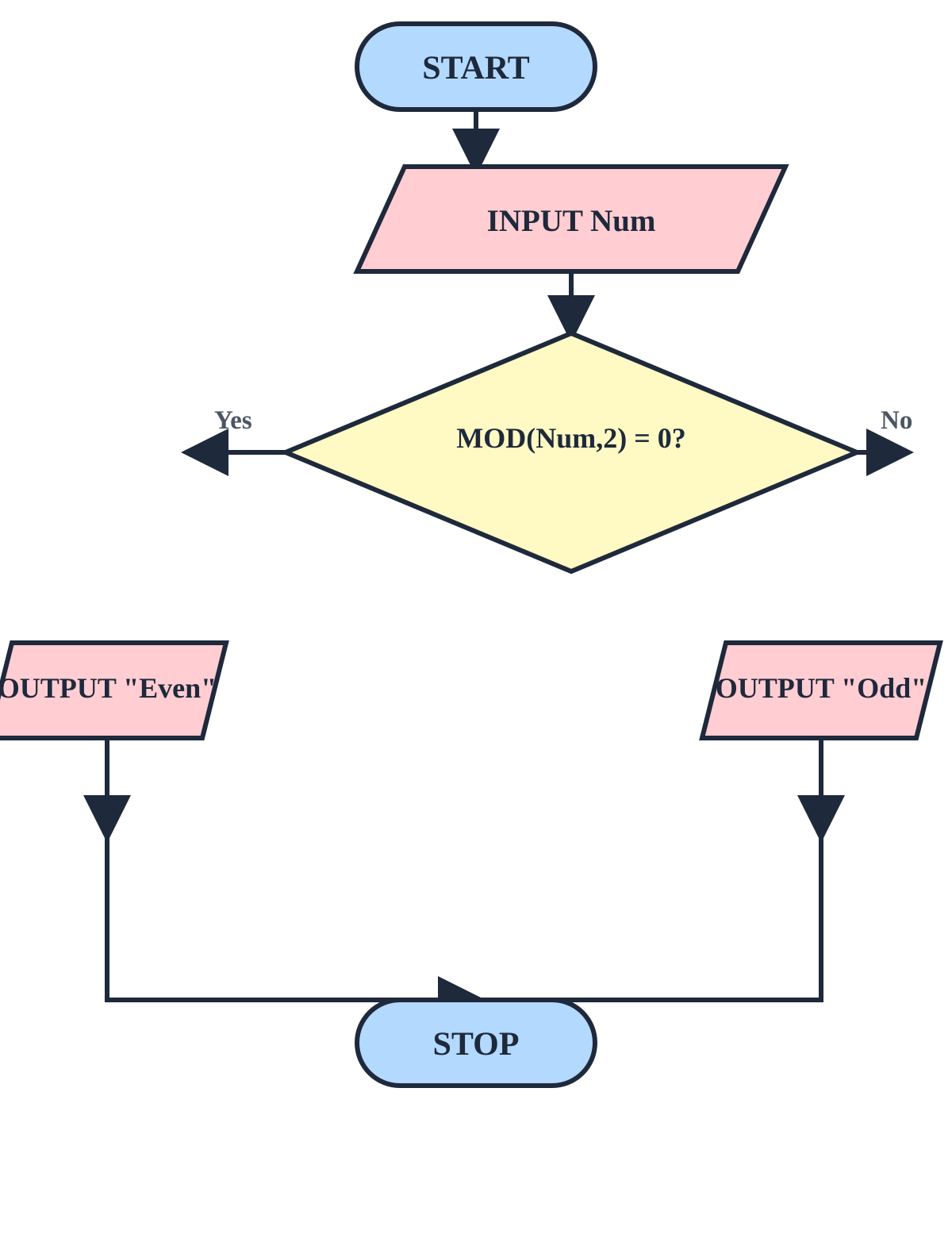
The decision diamond tests whether MOD(Num, 2) = 0. If the remainder is 0, the number is even and the left branch outputs "Even". If the remainder is not 0, the number is odd and the right branch outputs "Odd". Both branches merge at STOP.
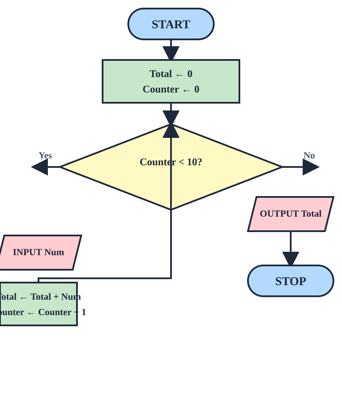
(a) Pre-condition loop (WHILE) — condition checked before body:
(b) Post-condition loop (REPEAT...UNTIL) — body executes first, then condition checked:
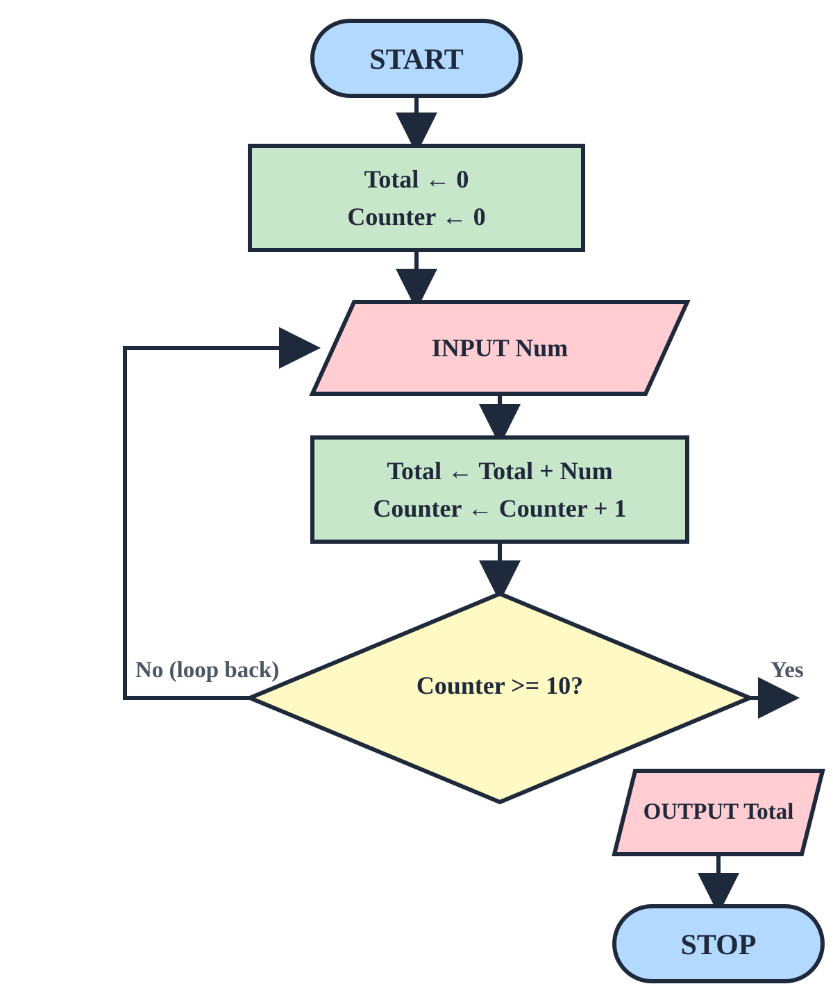
In the pre-condition flowchart, the condition Counter < 10? is checked before the loop body executes. In the post-condition flowchart, the body executes first, then the condition Counter >= 10? is checked — so the body always runs at least once.
| Structure Diagram | Flowchart |
|---|---|
| Represents the software architecture by breaking down a problem into more details with the help of modules. | Represents the flow of control in an algorithm with graphical design using a variety of boxes and arrows. |
| Easier to identify modules or sub-modules in a program. | Difficult to recognise and identify different modules. |
| Represents the structure in a hierarchical method. | Represents the flow of controls in a sequential structure. |
| Quite complex to understand and design. | Easier to construct and understand. |
Pseudocode
1) Assignment statement
The variable on the left of the ← operator is assigned a value or an expression using mathematical operators.
Example:
2) Selection (conditional) statement
Used when different actions need to be performed by an algorithm according to the values of the variables. There are two types:
(i) IF … THEN … ELSE … ENDIF — Conditional Selection:
Tests the given condition and executes the instructions if it is true or false, based on a relational operator (like <, >, =, AND, OR, NOT).
(ii) CASE … OF … OTHERWISE … ENDCASE — Conditional Switching:
Makes a choice and executes the instructions if it is true; based on the equality operator ( = ).
3) Iterative / Looping statement
Iteration is the term given to the repetition of a block of instructions within a computer program — for a fixed number of times, for as long as a condition is true, or until a condition becomes true. Iteration allows programmers to simplify a program and make it more efficient.
(i) FOR … TO … NEXT — Counting loop:
Executes a block of instructions repeatedly for a fixed number of times. The counter starts at the given value and is incremented by 1 each time until it reaches the limit.
(ii) WHILE … DO … ENDWHILE — Pre-conditional loop:
Executes the block of code and continues to loop only if the condition is True. It checks the condition before executing the body — so it may not execute even once.
(iii) REPEAT … UNTIL — Post-conditional loop:
Executes the body and continues to repeat until the condition becomes True (i.e. repeats only while the condition is False). The condition is checked after the body — so it must execute at least once. Often used for range-check validation.
(a) Pseudocode algorithm:
(b) Flowchart algorithm:
Comparing Flowchart and Pseudocode
(a) Similarity:
Both Flowchart and Pseudocode are tools used to represent an algorithm that illustrates a solution to a given problem and helps to develop software.
(b) Differences:
- A flowchart is a pictorial representation of an algorithm.
- Pseudocode is an informal high-level description of an algorithm.
(c) Choosing between flowchart and pseudocode — advantages and limitations:
The type of algorithm to use is chosen after analysing the time complexity and space complexity of an algorithm.
Flowchart — advantages:
- Easy to understand the logic of a given problem compared to pseudocode.
- Used in programming to show the steps to write a program.
Flowchart — limitation:
- Has a limitation of time and space complexity because it is a diagrammatic representation with various symbols.
Pseudocode — advantages:
- Independent of any specific programming language.
- Easier to write because you do not have to satisfy the restrictions of the syntax of a language — used when you want to express an idea quickly.
Effectiveness and Evaluation of Algorithms
In order to consider the effectiveness of a given solution, ask the following questions:
- Does the solution work for all sets of test data?
- Does the solution have any unnecessary process that is never used?
- Are any actions repeated unnecessarily?
- Can the solution be simplified and still work as well?
Evaluation is the process that allows us to make sure our algorithm does the job it has been designed to do and to think about how it could be improved.
Once an algorithm is written, it should be checked to make sure:
- It is easily understood — is it fully decomposed?
- It is complete — does it solve every aspect of the problem?
- It is efficient — does it solve the problem making best use of the available resources (e.g. as quickly as possible / using least space)?
- It meets any design criteria we have been given.
(a) Analysing efficiency:
An algorithm's efficiency can be judged in terms of:
- Speed — how quickly the algorithm produces the required output.
- Complexity of algorithm — how many lines of code the algorithm contains.
(b) Checking correctness:
Although an algorithm is expected to produce the correct outputs, correctness can still be measured in terms of:
- Accuracy — how many decimal places produce output with greater accuracy (e.g. more decimal places).
- Range — will the algorithm work with the complete range of inputs? Or only positive numbers, whole numbers, numbers below 1 million, etc.?
- Reliability — will the algorithm always produce correct output within the range it is designed to work? Or are there values which it will not accept (e.g. zero)?
(c) Checking appropriateness:
Appropriateness can be measured in terms of:
- Length — if the problem is simple then a short algorithm would normally be expected.
- Speed — if the output needs to be generated quickly, then the algorithm must be able to generate output quick enough.
- Memory requirements — an algorithm should use a minimum possible memory.
Revision: Statements and Key Computing Terms
| Statement | Key Term |
|---|---|
| Made up of software, data, hardware, communications and people; a set of integrated devices that input, process, output, communicate and store data and information. | Computer System |
| A part of a larger system that is derived from a system; an integral part that performs a single action but cannot provide a useful function by itself. | Sub-system |
| Decomposition of a computer system into sub-systems, breaking each sub-system down until each performs a single action. | Top-down Design |
| Breaking down a complex problem into smaller, more manageable parts. | Decomposition |
| A set of instructions telling a computer what to do step by step to solve a problem. | Algorithm |
| A hierarchical, top-down modular design tool that uses squares and lines to break a system into its sub-systems. | Structure Diagram |
| A diagram representing an algorithm using a variety of boxes and arrows to show the process and the direction of flow of data. | Flowchart |
| A method to describe the steps of an algorithm using English words and mathematical operators — not bound by any programming language's strict syntax. | Pseudocode |
| An oval shape in a flowchart that represents the Start or End of an algorithm. | Terminator |
| A parallelogram in a flowchart that represents input or output of data. | Input / Output |
| A rectangle in a flowchart that represents a process — used for arithmetical operations and data manipulations. | Process |
| A diamond in a flowchart that represents a decision on the direction of flow of data. | Decision |
| A statement that assigns a value or expression to a variable using the ← operator. | Assignment Statement |
| IF … THEN … ELSE … ENDIF or CASE … OF … OTHERWISE … ENDCASE. | Selection (Conditional) Statement |
| FOR … TO … NEXT, WHILE … DO … ENDWHILE, or REPEAT … UNTIL. | Iterative (Looping) Statement |
| A loop that checks the condition before executing the body — may not execute at all (e.g. WHILE … DO). | Pre-condition Loop |
| A loop that executes the body first, then checks the condition — must execute at least once (e.g. REPEAT … UNTIL). | Post-condition Loop |
| The process that allows us to make sure our algorithm does the job it has been designed to do and how it could be improved. | Evaluation |
| Judged in terms of speed (how quick the output is produced) and complexity (how many lines of code). | Efficiency |
| Measured in terms of accuracy, range and reliability of the algorithm's output. | Correctness |
| Measured in terms of length, speed and memory requirements of the algorithm. | Appropriateness |